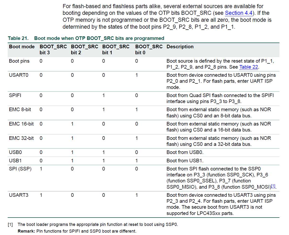
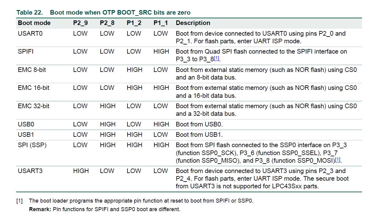
When programming and running code from the external flash, it is particularly important to make sure that you have the boot pins P2_9, P2_8, P1_2, and P1_1 are correctly connected so that the MCU starts execution from the correct memory address. For more details, please see the NXP documentation.
If the boot pins are incorrectly set, then this will typically result in the initial default breakpoint set by the debugger on main() not been reached. You can confirm if this is the case by clicking on suspend icon to pause execution (when you fail to hit the initial breakpoint) and then looking at the address of the PC. If you built for SPIFI, then the address of the PC should be 0x14xx xxxx, whereas if you built for EMC (SST), then the address of the PC should be0x1Cxx xxxx.
For example, for the Hitex LPC1850/4350 board, you need to have the BOOT jumpers configued as follows :
For SPIFI flash
For EMC SST flash
Note :
A power on reset is definitely required after changing the BOOT pin settings.
原文:http://www.cnblogs.com/shangdawei/p/4779272.html