一直想花时间来整理一下Linux内核LCD驱动,却一直都忙着做其他事情去了,这些天特意抽出时间来整理之前落下的笔记,故事就这样开始了。LCD驱动也是字符设备驱动的一种,框架上相对于字符设备驱动稍微复杂一点点,真的就是一点点,难点在对LCD硬件的配置上。
开发平台:TQ210,S5PV210处理器
内核版本:linux-3.10.46
LCD型号:AT070TN92,7英寸,TFT屏,分辨率800x480x3(RGB),24位真彩色
一、框架分析
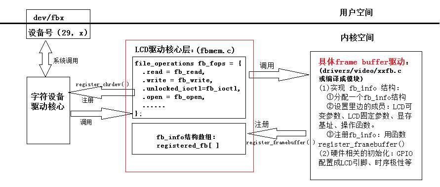
上图说明:①内核装载LCD驱动模块:设置并注册fb_info结构,初始化LCD硬件。②APP打开LCD设备,获取设备文件,根据设备文件进行读写显存。③在内核中,根据主设备号和次设备号定位一个fb_info结构,如果应用层的系统调用是读操作则调用fb_ops中对应的操作函数,写操作也是一样。
读写等操作代码分析:

 1 fb_open
 2 {
 3     int fbidx = iminor(inode);         //获取次设备号
 4     struct fb_info *info;
 5     info = get_fb_info(fbidx);
 6         struct fb_info *fb_info;
 7         fb_info = registered_fb[fbidx];//根据次设备号从已注册的fb_info数组中获取响应的结构
 8         return fb_info;
 9     ......
10     /*
11      * 从registered_fb[]数组项里找到fb_info结构体后,将其保存到
12      * struct file结构中的私有信息成员,难道这是为了以后在某些情况方便找到并调用??先放着...
13      * 回过来发现:这样做是为了验证在read、write、ioctl等系统调用中获得的fb_info结构和open获得的是否一样
14      */
15     file->private_data = info;
16     //info->fbops->fb_open无定义,这是值得思考的问题!
17     if (info->fbops->fb_open) {
18         res = info->fbops->fb_open(info,1);
19         if (res)
20             module_put(info->fbops->owner);
21     }
22     ......
23 }
 1 fb_read(struct file *file, char __user *buf, size_t count, loff_t *ppos)
 2 {
 3     struct fb_info *info = file_fb_info(file);
 4         struct inode *inode = file_inode(file);
 5         int fbidx = iminor(inode);
 6         //也是根据次设备号来获取fb_info结构
 7         struct fb_info *info = registered_fb[fbidx];
 8
 9         if (info != file->private_data)
10             info = NULL;
11         return info;
12     //无定义
13     if (info->fbops->fb_read)
14         return info->fbops->fb_read(info, buf, count, ppos);
15     //获得显存的大小
16     total_size = info->screen_size;
17     //如果应用层要读的数据count比实际最大的显存还要大,修改count值为最大显存值
18     if (count >= total_size)
19         count = total_size;
20     //分配显存,最大只能是一页PAGE_SIZE=4KB
21     buffer = kmalloc((count > PAGE_SIZE) ? PAGE_SIZE : count,GFP_KERNEL);
22     //要读的源地址:显存虚拟基地址+偏移
23     src = (u8 __iomem *) (info->screen_base + p);
24     while (count) {
25         c  = (count > PAGE_SIZE) ? PAGE_SIZE : count;
26         //读的目的地址
27         dst = buffer;
28         //读操作:拷贝数据
29         fb_memcpy_fromfb(dst, src, c);
30         dst += c;
31         src += c;
32
33         if (copy_to_user(buf, buffer, c)) {
34             err = -EFAULT;
35             break;
36         }
37         *ppos += c;
38         buf += c;
39         cnt += c;
40         count -= c;
41     }
42     kfree(buffer); //释放buffer,只起到临时中转站的作用
43 }
 1 /*
 2  * 这里分配的显存是在内核空间分配的,用户空间并不能直接访问,
 3  * 所以需要用到这里的mmap函数,直接将这段内存空间映射到
 4  * 用户空间去,用户空间就能访问这段内存空间了。
 5  */
 6 static int fb_mmap(struct file *file, struct vm_area_struct * vma)
 7 {
 8     struct fb_info *info = file_fb_info(file);
 9     struct fb_ops *fb;
10     unsigned long mmio_pgoff;
11     unsigned long start;
12     u32 len;
13
14     if (!info)
15         return -ENODEV;
16     fb = info->fbops;
17     if (!fb)
18         return -ENODEV;
19     mutex_lock(&info->mm_lock);
20     //如果fb_info->fbops->fb_mmap存在就调用该函数,实际中没有!
21     if (fb->fb_mmap) {
22         int res;
23         res = fb->fb_mmap(info, vma);
24         mutex_unlock(&info->mm_lock);
25         return res;
26     }
27
28     /*
29      * Ugh. This can be either the frame buffer mapping, or
30      * if pgoff points past it, the mmio mapping.
31      */
32     start = info->fix.smem_start; //fb缓冲内存的开始位置(物理地址)
33     len = info->fix.smem_len;
34     mmio_pgoff = PAGE_ALIGN((start & ~PAGE_MASK) + len) >> PAGE_SHIFT;
35     if (vma->vm_pgoff >= mmio_pgoff) {
36         if (info->var.accel_flags) {
37             mutex_unlock(&info->mm_lock);
38             return -EINVAL;
39         }
40
41         vma->vm_pgoff -= mmio_pgoff;
42         start = info->fix.mmio_start;
43         len = info->fix.mmio_len;
44     }
45     mutex_unlock(&info->mm_lock);
46
47     vma->vm_page_prot = vm_get_page_prot(vma->vm_flags);
48     fb_pgprotect(file, vma, start);
49     //映射物理内存到用户空间虚拟地址
50     return vm_iomap_memory(vma, start, len);
51 }
问题思考:
问1.什么叫帧缓冲区,他有哪些特性指标?
答1.对于应用层来说,显示图像到LCD设备就相当于往“一块内存”中写入数据,获取LCD设备上的图像就相当于拷贝“这块内存”中的数据。因此,LCD就和“一块内存”一样,专业一点术语叫帧缓冲区,它和普通的内存不太一样,除了可以“读写”操作之外还可以进行其他操作和功能设置,特性指标就是LCD的特性指标。在内核中,一个LCD显示器就相当于一个帧缓冲设备,对应一个fb_info结构。
问2.为什么要通过 registered_fb[] 数组来找到对应的 fb_info 结构体?
答2.通过对上边这几个函数的剖析发现,不管是fb_read、fb_write、fb_ioctl、fb_mmap系统调用,都是通过次设备号在已注册的fb_info结构数组中找到匹配的那一个结构之后,判断其中的fbops结构中的操作函数是否有定义,有的话就优先调用该函数,没有就使用往下的方案策略。这样的好处就是多个相同的LCD设备可以使用同一套代码,减少代码的重复性,同时对于需要特殊定义的函数又可以方便实现重定义。
问3.这个数组在哪里被注册?
答3.在register_framebuffer()函数中被注册 register_framebuffer(struct fb_info *fb_info) ret = do_register_framebuffer(fb_info); ...... registered_fb[i] = fb_info; ......
问4.fb_mmap()函数在什么场合使用?
答4.在用户空间中通过mmap()函数来进行系统调用,该函数执行成功返回的是指向被映射的帧缓冲区的指针,这样用户直接可以通过该指针来读写缓冲区。
二、驱动代码编写
#include <linux/module.h>
#include <linux/kernel.h>
#include <linux/errno.h>
#include <linux/string.h>
#include <linux/mm.h>
#include <linux/slab.h>
#include <linux/delay.h>
#include <linux/fb.h>
#include <linux/init.h>
#include <linux/dma-mapping.h>
#include <linux/interrupt.h>
#include <linux/platform_device.h>
#include <linux/clk.h>
#include <linux/workqueue.h>

#include <asm/io.h>
#include <asm/div64.h>
#include <asm/uaccess.h>

#include <asm/mach/map.h>
#include <mach/regs-gpio.h>
#include <linux/fb.h>

#define VSPW        9   //4
#define VBPD        13  //17
#define LINEVAL     479
#define VFPD        21  //26

#define HSPW        19    //4
#define HBPD        25   //40
#define HOZVAL      799
#define HFPD        209   //214

#define LeftTopX    0
#define LeftTopY    0
#define RightBotX   799
#define RightBotY   479

static struct fb_info *clb_fbinfo;

/* LCD GPIO Pins */
static long unsigned long *gpf0con;
static long unsigned long *gpf1con;
static long unsigned long *gpf2con;
static long unsigned long *gpf3con;
static long unsigned long *gpd0con;
static long unsigned long *gpd0dat;
static long unsigned long *display_control;

/* LCD Controler Pins */
struct s5pv210_lcd_regs{
    volatile unsigned long vidcon0;
    volatile unsigned long vidcon1;
    volatile unsigned long vidcon2;
    volatile unsigned long vidcon3;

    volatile unsigned long vidtcon0;
    volatile unsigned long vidtcon1;
    volatile unsigned long vidtcon2;
    volatile unsigned long vidtcon3;

    volatile unsigned long wincon0;
    volatile unsigned long wincon1;
    volatile unsigned long wincon2;
    volatile unsigned long wincon3;
    volatile unsigned long wincon4;

    volatile unsigned long shadowcon;
    volatile unsigned long reserve1[2];

    volatile unsigned long vidosd0a;
    volatile unsigned long vidosd0b;
    volatile unsigned long vidosd0c;
};

struct clk      *lcd_clk;
static struct s5pv210_lcd_regs *lcd_regs;

static long unsigned long *vidw00add0b0;
static long unsigned long *vidw00add1b0;

static u32  pseudo_palette[16];

/* from pxafb.c */
static  unsigned int chan_to_field(unsigned int chan, struct fb_bitfield *bf)
{
    chan &= 0xffff;
    chan >>= 16 - bf->length;
    return chan << bf->offset;
}

static int  clb210_lcdfb_setcolreg(unsigned regno,
                   unsigned red, unsigned green, unsigned blue,
                   unsigned transp, struct fb_info *info)
{
    unsigned int val;

    if (regno > 16)
        return 1;

    /* 用red,green,blue三原色构造出val */
    val  = chan_to_field(red,   &info->var.red);
    val |= chan_to_field(green, &info->var.green);
    val |= chan_to_field(blue,  &info->var.blue);

    pseudo_palette[regno] = val;

    return 0;
}

//帧缓冲操作函数
static struct fb_ops clb210_lcdfb_ops =
{
    .owner            = THIS_MODULE,
    .fb_setcolreg    = clb210_lcdfb_setcolreg,
    //下面这3个函数是通用的
    .fb_fillrect    = cfb_fillrect,
    .fb_copyarea    = cfb_copyarea,
    .fb_imageblit    = cfb_imageblit,
};

static int  __init clb210_lcd_init(void)
{
    /* 1.分配一个fb_info */
    clb_fbinfo = framebuffer_alloc(0 , NULL);

    /* 2. 设置 */
    /* 2.1 设置固定的参数 */
    strcpy(clb_fbinfo->fix.id, "clb210_lcd");
    clb_fbinfo->fix.smem_len = 800 * 480 * 32/8;
    clb_fbinfo->fix.type = FB_TYPE_PACKED_PIXELS;
    clb_fbinfo->fix.visual = FB_VISUAL_TRUECOLOR;
    clb_fbinfo->fix.line_length = 800 * 32/8;

    /* 2.2 设置可变的参数 */
    clb_fbinfo->var.xres = 800;
    clb_fbinfo->var.yres = 480;
    clb_fbinfo->var.xres_virtual   = 800;
    clb_fbinfo->var.yres_virtual   = 480;
    clb_fbinfo->var.bits_per_pixel = 32;

    /*RGB:888*/
    clb_fbinfo->var.red.offset = 16;
    clb_fbinfo->var.red.length = 8;

    clb_fbinfo->var.green.offset = 8;
    clb_fbinfo->var.green.length = 8;

    clb_fbinfo->var.blue.offset = 0;
    clb_fbinfo->var.blue.length = 8;

    clb_fbinfo->var.activate = FB_ACTIVATE_NOW    ;

    /* 2.3 设置操作函数 */
    clb_fbinfo->fbops = &clb210_lcdfb_ops;

    /* 2.4 其他的设置 */
    /* 2.4.1 设置显存的大小 */
    clb_fbinfo->screen_size =  800 * 480 * 32/8;

    /* 2.4.2 设置调色板 */
    clb_fbinfo->pseudo_palette = pseudo_palette;

    /* 2.4.3 设置显存的虚拟起始地址 */
    clb_fbinfo->screen_base = dma_alloc_writecombine(NULL,
            clb_fbinfo->fix.smem_len, (u32*)&(clb_fbinfo->fix.smem_start), GFP_KERNEL);


    /* 3. 硬件相关的操作 */
    /* 3.1 获取lcd时钟,使能时钟 */
    lcd_clk = clk_get(NULL, "lcd");
    if (!lcd_clk || IS_ERR(lcd_clk)) {
        printk(KERN_INFO "failed to get lcd clock source\n");
    }
    clk_enable(lcd_clk);

    /* 3.2 配置GPIO用于LCD */
    gpf0con = ioremap(0xE0200120, 4);
    gpf1con = ioremap(0xE0200140, 4);
    gpf2con = ioremap(0xE0200160, 4);
    gpf3con = ioremap(0xE0200180, 4);
    gpd0con = ioremap(0xE02000A0, 4);
    gpd0dat = ioremap(0xE02000A4, 4);
    display_control = ioremap(0xe0107008, 4);

    /* 设置相关GPIO引脚用于LCD */
    *gpf0con = 0x22222222;
    *gpf1con = 0x22222222;
    *gpf2con = 0x22222222;
    *gpf3con = 0x22222222;

    /* 使能LCD本身 */
    *gpd0con |= 1<<4;
    *gpd0dat |= 1<<1;

    /* 显示路径的选择, 0b10: RGB=FIMD I80=FIMD ITU=FIMD */
    *display_control  = 2<<0;

    /* 3.3 映射LCD控制器对应寄存器 */
    lcd_regs = ioremap(0xF8000000, sizeof(struct s5pv210_lcd_regs));
    vidw00add0b0 = ioremap(0xF80000A0, 4);
    vidw00add1b0 = ioremap(0xF80000D0, 4);

    lcd_regs->vidcon0 &= ~((3<<26) | (1<<18) | (0xff<<6)  | (1<<2));
    lcd_regs->vidcon0 |= ((5<<6) | (1<<4) );

    lcd_regs->vidcon1 &= ~(1<<7);            /* 在vclk的下降沿获取数据 */
    lcd_regs->vidcon1 |= ((1<<6) | (1<<5));  /* HSYNC极性反转, VSYNC极性反转 */

    lcd_regs->vidtcon0 = (VBPD << 16) | (VFPD << 8) | (VSPW << 0);
    lcd_regs->vidtcon1 = (HBPD << 16) | (HFPD << 8) | (HSPW << 0);
    lcd_regs->vidtcon2 = (LINEVAL << 11) | (HOZVAL << 0);
    lcd_regs->wincon0 &= ~(0xf << 2);
    lcd_regs->wincon0 |= (0xB<<2)|(1<<15);
    lcd_regs->vidosd0a = (LeftTopX<<11) | (LeftTopY << 0);
    lcd_regs->vidosd0b = (RightBotX<<11) | (RightBotY << 0);
    lcd_regs->vidosd0c = (LINEVAL + 1) * (HOZVAL + 1);

    *vidw00add0b0 = clb_fbinfo->fix.smem_start;
    *vidw00add1b0 = clb_fbinfo->fix.smem_start + clb_fbinfo->fix.smem_len;

    lcd_regs->shadowcon = 0x1;  /* 使能通道0 */
    lcd_regs->vidcon0  |= 0x3;  /* 开启总控制器 */
    lcd_regs->wincon0 |= 1;     /* 开启窗口0 */


    /*4.注册*/
    register_framebuffer(clb_fbinfo);

    return 0;
}
static void __exit clb210_lcd_exit(void)
{
    unregister_framebuffer(clb_fbinfo);
    dma_free_writecombine(NULL,  clb_fbinfo->fix.smem_len, clb_fbinfo->screen_base, clb_fbinfo->fix.smem_start);
    iounmap(gpf0con);
    iounmap(gpf1con);
    iounmap(gpf2con);
    iounmap(gpf3con);
    iounmap(gpd0con);
    iounmap(gpd0dat);
    iounmap(display_control);
    iounmap(lcd_regs);
    iounmap(vidw00add0b0);
    iounmap(vidw00add1b0);
    framebuffer_release(clb_fbinfo);
}

module_init(clb210_lcd_init);
module_exit(clb210_lcd_exit);

MODULE_LICENSE("GPL");
MODULE_AUTHOR("clb");
MODULE_DESCRIPTION("Lcd driver for clb210 board");
这份代码没有基于platform设备驱动来编写,在内核源码中的demo就是基于platform驱动模型来搭建的,主要内容其实一样。
三、编译测试
(1) 进入内核源码目录中,make menuconfig -> Device Drivers -> Graphics support -> [M]Support for frame buffer devices
重新编译内核 make uImage ,然后make modules,将driver/video/下的 fb.ko、cfbfillrect.ko、cfbimgblt.ko、cfbcopyarea.ko拷贝到210的根文件中,分别 insmod 安装到内核中。
(2) 安装lcd.ko驱动模块
(3) 应用层读写 frame buffer 测试程序
原文:http://www.cnblogs.com/lubiao/p/4850258.html
