vtkPlanes 为一组平面计算他们的隐函数和函数梯度。这些平面必须定义一个凸空间。函数值是一点到平面所定义的凸域的最近一阶距离。函数梯度是平面法向量的函数值。注意,法向量必须指向凸域的外边。这样当函数值为负数时,表示该点在凸域内部。
有多种方法定义一组平面。最常见的方法是,提供vtkPoints和vtkDataArray的实例。vtkPoints定义了平面上的点和平面法向量的方向。
还有两种方法:(1)提供6个平面,定义一个相机视角平截头体( view frustrum of a camera,)
(2)提供一个a bounding box.
The function value is the closest first order distance of a point to the convex region defined by the planes. The function gradient is the plane normal at the function value. Note that the normals must point outside of the convex region. Thus, a negative function value means that a point is inside the convex region.
There are several methods to define the set of planes. The most general is to supply an instance of vtkPoints and an instance of vtkDataArray. (The points define a point on the plane, and the normals corresponding plane normals.) Two other specialized ways are to 1) supply six planes defining the view frustrum of a camera, and 2) provide a bounding box.
vtkAppendPolyData is a filter that appends one of more polygonal datasets into a single polygonal dataset. All geometry is extracted and appended, but point and cell attributes (i.e., scalars, vectors, normals) are extracted and appended only if all datasets have the point and/or cell attributes available. (For example, if one dataset has point scalars but another does not, point scalars will not be appended.)
将方向、尺度缩放后的几何符号,复制到每个输入点上。copy oriented and scaled glyph geometry to every input point
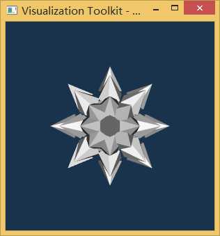
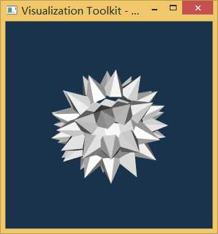
vtkGlyph3D 是一个筛选器,它可以将一个几何图形复制到输入数据(dataset)中的每个点上,这个被复制的几何图形称为符号(glyph)。向该类中传入一个source filter,比如本例中的cone,根据cone的多边形数据定义glyph。glyph的方向可以与输入的矢量或法向量一致,还可以根据标量数据(scalar data)或这矢量幅值(vector magnitude)缩放glyp的尺度。当有多个glyph时,就需要建立一个source object表,表中的每一个source object定义一个不同的glyph。如果一个glyphs表已经建立,那么可以根据scalar data或vector magnitude对表格进行检索。
为了能够使用该类的对象,你需要为其输入一个数据集(dataset)和一个source,source用来定义glyph的形状。然后,决定是否对glyph进行尺度缩放,以及是根据scalar还是根据vector magnitude进行缩放。接下来,决定你是否想要为glyph确定方向,以及是使用vector还是normal确定方向。最后,决定是使用glyphs表还是一种简单的符号形状。如果使用符号表,你还需要决定是用scalar还是用vector magnitude对其索引。
glyph->SetInputConnection(sphere->GetOutputPort());//将锥型符号复制到球面的每个点上,DataSet数据集,在本例中为球面上各个的点,将锥型符号复制到这些点上,并且指向该点的法向方向。
glyph->SetSourceConnection(cone->GetOutputPort());//创建锥型符号vtkConeSource
glyph->SetVectorModeToUseNormal();//将矢量模式改成法向量模式
glyph->SetScaleModeToScaleByVector();//根据矢量幅值缩放锥型符号
glyph->SetScaleFactor(0.25);//设定锥型符号的缩放比例为0.25
#ifndef INITIAL_OPENGL
#define INITIAL_OPENGL
#include <vtkAutoInit.h>
VTK_MODULE_INIT(vtkRenderingOpenGL)
VTK_MODULE_INIT(vtkInteractionStyle)
#endif
#include <iostream>
using namespace std;
#include <vtkSphereSource.h>
#include <vtkConeSource.h>
#include <vtkGlyph3D.h>
#include <vtkAppendPolyData.h>
#include <vtkPolyDataMapper.h>
#include <vtkLODActor.h>
#include <vtkClipPolyData.h>
#include <vtkRenderer.h>
#include <vtkRenderWindow.h>
#include <vtkRenderWindowInteractor.h>
#include <vtkInteractorStyleTrackballCamera.h>
#include <vtkProperty.h>
#include <vtkBoxWidget.h>
#include <vtkCommand.h>
#include <vtkObject.h>
#include <vtkPlanes.h>

class myCommand:public vtkCommand
{
public:
    static myCommand *New(){return new myCommand;}
    void setObject(vtkBoxWidget* bw,vtkLODActor* lodActor,vtkPlanes*plan)
    {
        boxWidget=bw;
        selectActor=lodActor;
        planes=plan;
    }
    virtual void Execute(vtkObject*caller,unsigned long EventIds,void* callData)
    {
        boxWidget->GetPlanes(planes);
        selectActor->VisibilityOn();
    }


private:
    vtkBoxWidget *boxWidget;
    vtkLODActor *selectActor;
    vtkPlanes *planes;
};

int main()
{
/* Demonstrate how to use the vtkBoxWidget 3D widget,
 This script uses a 3D box widget to define a "clipping box" to clip some
 simple geometry (a mace). Make sure that you hit the "W" key to activate the widget.
*/
// Create a mace out of filters.
    vtkSmartPointer<vtkSphereSource>sphere=vtkSmartPointer<vtkSphereSource>::New();
    vtkSmartPointer<vtkConeSource> cone=vtkSmartPointer<vtkConeSource> ::New();
    vtkSmartPointer<vtkGlyph3D> glyph=vtkSmartPointer<vtkGlyph3D>::New();
    glyph->SetInputConnection(sphere->GetOutputPort());//将锥型符号复制到球面的每个点上
    glyph->SetSourceConnection(cone->GetOutputPort());//创建锥型符号
    glyph->SetVectorModeToUseNormal();//将矢量模式改成法向量模式
    glyph->SetScaleModeToScaleByVector();//根据矢量幅值缩放锥型符号
    glyph->SetScaleFactor(0.25);//设定锥型符号的缩放比例为0.25

    //将sphere和spikes附加到一个PolyData中,这样可以方便管理
    vtkSmartPointer<vtkAppendPolyData> apd=vtkSmartPointer<vtkAppendPolyData>::New();
    apd->AddInputConnection(glyph->GetOutputPort());
//    apd->AddInputConnection(sphere->GetOutputPort());
    vtkSmartPointer<vtkPolyDataMapper> maceMapper=vtkSmartPointer<vtkPolyDataMapper>::New();
    maceMapper->SetInputConnection(apd->GetOutputPort());
    vtkSmartPointer<vtkLODActor> maceActor=vtkSmartPointer<vtkLODActor>::New();
    maceActor->SetMapper(maceMapper);
    maceActor->VisibilityOn();
    //下面的代码是用tkPlanes的隐函数,对mace进行裁剪。被裁剪的区域染成了绿色
    vtkSmartPointer<vtkPlanes> planes=vtkSmartPointer<vtkPlanes>::New();
    vtkSmartPointer<vtkClipPolyData> clipper=vtkSmartPointer<vtkClipPolyData>::New();
    clipper->SetInputConnection(apd->GetOutputPort());
    clipper->SetClipFunction(planes);
    clipper->InsideOutOn();
    vtkSmartPointer<vtkPolyDataMapper> selectMapper=vtkSmartPointer<vtkPolyDataMapper>::New();
    selectMapper->SetInputConnection(clipper->GetOutputPort());
    vtkSmartPointer<vtkLODActor> selectActor=vtkSmartPointer<vtkLODActor>::New();
    selectActor->SetMapper(selectMapper);
    selectActor->GetProperty()->SetColor(0,1,0);
    selectActor->VisibilityOff();
    selectActor->SetScale(1.01,1.01,1.01);
    //创建显示窗口
    vtkSmartPointer<vtkRenderer> ren1=vtkSmartPointer<vtkRenderer>::New();
    vtkSmartPointer<vtkRenderWindow> renWin=vtkSmartPointer<vtkRenderWindow>::New();
    vtkSmartPointer<vtkRenderWindowInteractor> iren=vtkSmartPointer<vtkRenderWindowInteractor>::New();

    renWin->AddRenderer(ren1);
    iren->SetRenderWindow(renWin);
//SetIneractor方法,用于3Dwidgets与渲染窗口互动器vtkRenderWindowInteractor之间的链接
    vtkSmartPointer<vtkBoxWidget> boxWidget=vtkSmartPointer<vtkBoxWidget>::New();
    boxWidget->SetInteractor(iren);
    boxWidget->SetPlaceFactor(1.25);
    //将两个演员添加到renderer,并设置背景颜色和尺寸
    ren1->AddActor(maceActor);
    ren1->AddActor(selectActor);
    ren1->SetBackground(0.1,0.2,0.3);
    renWin->SetSize(300,300);

    ///配置初始互动器,3D widget的输入被用来初始化widget的位置和比例。
    /// 当出现EndInteractionEvent事件时,将触发回调函数 SelectPolygons callback
    vtkSmartPointer<myCommand> callback=vtkSmartPointer<myCommand>::New();
    callback->setObject(boxWidget,selectActor,planes);
    boxWidget->SetInputConnection(glyph->GetOutputPort());
    boxWidget->PlaceWidget();
    boxWidget->AddObserver(vtkCommand::EndInteractionEvent,callback);
    iren->Initialize();
    renWin->Render();
    iren->Start();
    return 0;
}
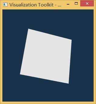
vtkPlaneSource 用于创建一个 m x n的四边形数组,这些四边形以像瓷砖一样贴在一个平面上。这个平面由原点和其它两个点来确定,在平面原点还定义了两个轴(axes)。这两个轴不必正交,但必须平行,这样可以方便你创建平行四边形。平面的分辨率(即,子区间的个数)通过变量XResolution and YResolution来控制。分别通过SetXResolution、SetYResolution两个方法实现分辨率的设置,相反的也可以通过GetXResolution、GetYResolution这两个方法获取这两个分辨率值。默认情况下,平面中心位于原点,与z-axis正交,平面的width和height为1,分辨率为1。
There are three convenience methods that allow you to easily move the plane. The first, SetNormal(), allows you to specify the plane normal. The effect of this method is to rotate the plane around the center of the plane, aligning the plane normal with the specified normal. The rotation is about the axis defined by the cross product of the current normal with the new normal. The second, SetCenter(), translates the center of the plane to the specified center point. The third method, Push(), allows you to translate the plane along the plane normal by the distance specified. (Negative Push values translate the plane in the negative normal direction.) Note that the SetNormal(), SetCenter() and Push() methods modify the Origin, Point1, and/or Point2 instance variables.
该类中有三个便利的方法(即成员函数),帮助你很容易的移动平面。首先,SetNormal(), 允许你指定平面的法向量(plane normal)。这个方法的效果,就是使平面绕着平面中心转动,指向你所规定的方向。所谓的旋转,就是通过将当前平面的法向量与你所指定的法向量叉乘来实现的。第二,SetCenter(), 可以实现平面平移到你所指定的中心点坐标。第三, Push(), 是你能够将平面沿着法向量方向平移你所指定的距离,这是个非常有用的函数方法。如果Push的参数是负值,平面就沿着法向量的反方向移动。注意, SetNormal(), SetCenter() and Push() 这三个方法,修改了Origin、Point1和Point2实例变量。
 1 #ifndef INITIAL_OPENGL
 2 #define INITIAL_OPENGL
 3 #include <vtkAutoInit.h>
 4 VTK_MODULE_INIT(vtkRenderingOpenGL)
 5 VTK_MODULE_INIT(vtkInteractionStyle)
 6 #endif
 7 #include <iostream>
 8 using namespace std;
 9 #include <vtkVersion.h>
10 #include <vtkPlaneSource.h>
11 #include <vtkPolyData.h>
12 #include <vtkSmartPointer.h>
13 #include <vtkPolyDataMapper.h>
14 #include <vtkActor.h>
15 #include <vtkRenderWindow.h>
16 #include <vtkRenderer.h>
17 #include <vtkRenderWindowInteractor.h>
18
19 int main()
20 {
21     //创建一个平面
22     vtkSmartPointer<vtkPlaneSource>planeSource=vtkSmartPointer<vtkPlaneSource>::New();
23     planeSource->SetCenter(1,0,0);
24     planeSource->SetNormal(1,1,1);
25     planeSource->Update();
26 //planeSource会根据上面输入数据,创建PolyData对象,并通过GetOutput输出对象指针
27     vtkSmartPointer<vtkPolyData> polydataPlane=vtkSmartPointer<vtkPolyData>::New();
28     polydataPlane=planeSource->GetOutput();
29     vtkSmartPointer<vtkPolyDataMapper> mapper=vtkSmartPointer<vtkPolyDataMapper>::New();
30     mapper->SetInputData(polydataPlane);
31     //创建演员
32     vtkSmartPointer<vtkActor> actor=vtkSmartPointer<vtkActor>::New();
33     actor->SetMapper(mapper);
34
35 //创建显示窗口
36     vtkSmartPointer<vtkRenderer> renderer = vtkSmartPointer<vtkRenderer>::New();
37     vtkSmartPointer<vtkRenderWindow> renderWindow = vtkSmartPointer<vtkRenderWindow>::New();
38     renderWindow->AddRenderer(renderer);
39     vtkSmartPointer<vtkRenderWindowInteractor> renderWindowInteractor = vtkSmartPointer<vtkRenderWindowInteractor>::New();
40     renderWindowInteractor->SetRenderWindow(renderWindow);
41
42     // Add the actors to the scene
43     renderer->AddActor(actor);
44     renderer->SetBackground(.1,.2,.3); // Background color dark blue
45
46     // Render and interact
47     renderWindow->Render();
48     renderWindowInteractor->Start();
49     return 0;
50 }
原文:http://www.cnblogs.com/phoenixdsg/p/6241318.html