这是一个双二选1多路选择器的原理图,用VHDL语言描述,需要用到元器件例化语句。
首先编写2选一多路选择器。
entity mux21a is
port(a,b,c:in bit;
y:out bit
);
end;
architecture bhv of mux21a is
begin
process(a,b,c)
begin
if s=‘0‘ then y<=a; else y<=b;
end if;
end process;
end architecture bhv;
其电路逻辑:当y输出高电平‘1‘时,s=‘0‘,a=1(b不考虑)
s=‘1‘,b=1(a不考虑)
当y输出低电平‘0’时,s=‘0‘,a=0(b不考虑)
s=‘1‘,b=0(a不考虑)
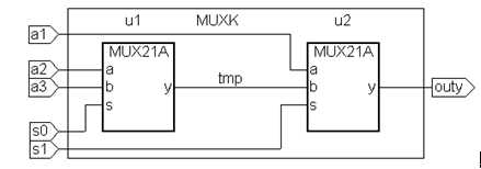
双2选1多路选择器程序
entity muxk is
port(a1,a2,a3,s0,s1:in bit;
outy:out bit
);
end;
architecture bhv of muxk is
component mux21a
port(a,b,s:in bit;
y:out bit
);
end component;
signal tmp:bit;
begin
u1:mux21a port map(a=>a2,b=>a3,s=>s0,y=>tmp);
u2:mux21a port map(a=>a1,b=>tmp,s=>s1,y=>outy);
end architecture bhv;
其电路逻辑:当输出为高电平‘1‘时,s1=0.a1=1(s0,a2,a3不考虑)
s1=1,s0=0,a2=1(a1,a3不考虑)
s0=1,a3=1(a1,a2不考虑)
当输出为低电平‘0‘时,s1=0,a1=0(s0,a2,a3不考虑)
s1=1, s0=0,a2=0(a1,a3不考虑)
s1=1,s0=1,a3=0(a1,a2不考虑)
VHDL例化语句
例化语句由两部分组成,第一部分是将一个现成的设计实体定义为一个元件,语句的功能是对待调用的这个元器件做出调用声明。格式如下:
component 元件名 is
port(端口名)
end component;
元件定义语句必须放在结构体的architecture和begin之间。
端口信号的数据类型的定义必须与原设计实体文件一致,而且信号的排列方式也要与原来一致,包括端口模式、数据类型、功能定义等。
元件例化语句的第二部分则是此元件与当前设计实体(顶层文件)中元件间及端口的连接说明。
例化名:元件名 port map([端口名=>]连接端口名.....);
port map是端口映射,或端口连接的意思。其中的“端口名”是在元件定义语句中的端口名表中已定义好元件端口的名字。
“=>”仅代表连接关系,不代表信号流动的方向。
原文:https://www.cnblogs.com/lhkhhk/p/11793410.html