一、定位故障
#errpt
#errpt -aj XXXXXX
或者通过ASMI登陆查询error错误信息
二、更换准备
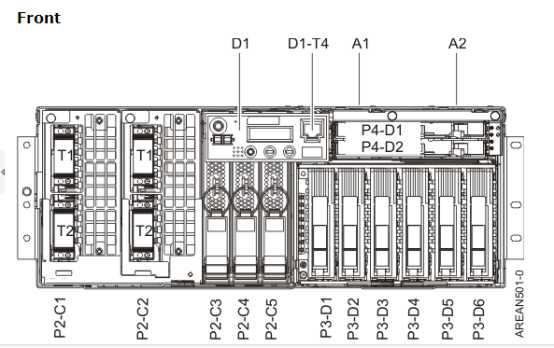
Determining memory slot locations for processor features 5620, 5622, 7380, 7387, 7388, and 7540
Determine the slots in which the memory modules will be placed.
Notes
- All memory module configurations are ordered and installed with memory in groups of four (quads) in each processor assembly.
- A minimum of four memory modules is required in each processor assembly for proper system operation, and all four memory modules must be the same size.
- Every processor card must have at least 4 GB of memory installed.
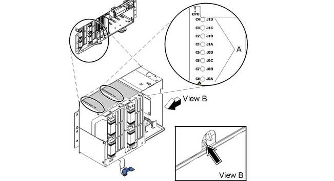
- Each processor assembly has 12 memory module slots. See Figure 2 for the memory module slot locations in the processor assembly. The memory modules must be plugged into the slots in the following order:
- Plug the first quad of memory modules into slots J0A, J0B, J0C, and J0D.
- Plug the second quad of memory modules into slots J1A, J1B, J1C, and J1D.
- Plug the third quad of memory modules into slots J2A, J2B, J2C, and J2D.
Figure 2. Memory module slot locations in the processor assembly for processor features 5620, 5622, 7380, 7387, 7388, and 7540
- A quad set of 8 GB memory modules cannot be mixed with memory modules of smaller size on a processor card.
- With the exception of the 8 GB and 16 GB memory modules, quads of memory can be mixed on a processor card. If the quads of memory are mixed, the memory will run at the lowest frequency of the installed memory.
- For a fully configured system, fill the quads according to the order shown in Table 1. When adding memory modules, begin with the first open quad. If the system is not fully configured, eliminate the appropriate number of enclosures and processor cards.
|
Table 1. Memory module plugging order for processor features 5620, 5622, 7380, 7387, 7388, and 7540
|
|
System unit
|
Slot locations for memory
|
Enclosure 1
|
Enclosure 2
|
Enclosure 3
|
Enclosure 4
|
|
Processor
|
|
1
|
2
|
3
|
4
|
5
|
6
|
7
|
8
|
|
Single-enclosure system
|
J0A, J0B, J0C, J0D
|
1
|
|
|
|
|
|
|
|
|
J1A, J1B, J1C, J1D
|
2
|
|
|
|
|
|
|
|
|
J2A, J2B, J2C, J2D
|
3
|
|
|
|
|
|
|
|
|
Single-enclosure system
|
J0A, J0B, J0C, J0D
|
1
|
2
|
|
|
|
|
|
|
|
J1A, J1B, J1C, J1D
|
4
|
3
|
|
|
|
|
|
|
|
J2A, J2B, J2C, J2D
|
5
|
6
|
|
|
|
|
|
|
|
Two-enclosure system
|
J0A, J0B, J0C, J0D
|
1
|
2
|
3
|
4
|
|
|
|
|
|
J1A, J1B, J1C, J1D
|
8
|
7
|
6
|
5
|
|
|
|
|
|
J2A, J2B, J2C, J2D
|
9
|
10
|
11
|
12
|
|
|
|
|
|
Three-enclosure system
|
J0A, J0B, J0C, J0D
|
1
|
2
|
3
|
4
|
5
|
6
|
|
|
|
J1A, J1B, J1C, J1D
|
12
|
11
|
10
|
9
|
8
|
7
|
|
|
|
J2A, J2B, J2C, J2D
|
13
|
14
|
15
|
16
|
17
|
18
|
|
|
|
Four-enclosure system
|
J0A, J0B, J0C, J0D
|
1
|
2
|
3
|
4
|
5
|
6
|
7
|
8
|
|
J1A, J1B, J1C, J1D
|
16
|
15
|
14
|
13
|
12
|
11
|
10
|
9
|
|
J2A, J2B, J2C, J2D
|
17
|
18
|
19
|
20
|
21
|
22
|
23
|
24
|
三、更换步骤
1、 Power off the system and remove the power cords:
|
Power off the system and remove the power cords:
- Before continuing ensure the device is not being used by the customer.
- If possible, shut down any running applications and the operating system before powering off the system.
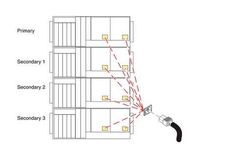
- After the system is powered off, remove all power cords from all of the processor enclosures, starting with the primary processor enclosure (topmost) and then each secondary enclosure, working from top to bottom.
|
|
|
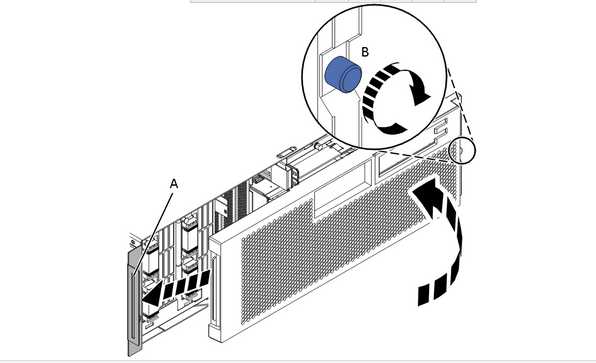
2、 Remove the Front Cover
- Open the front rack door.
- Loosen the thumbscrew (A) on the right side of the cover.
- Slide the cover to the right and remove it from the system unit slot (B).
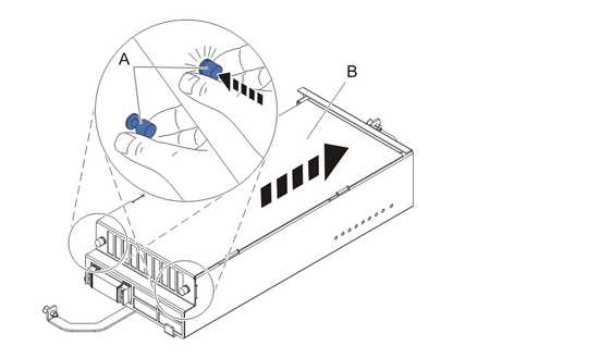
3、Disconnect the SMP Cable
- Carefully pull the handle (A) from the system until the connector is unseated.
- When the guide pins (B) are free, carefully pull the SMP processor cable away from the system unit.
Repeat these steps for all SMP cable connectors that are present on the system you are servicing.
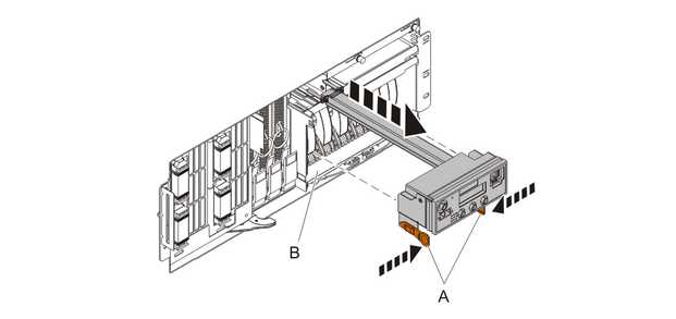
4、 Remove the Control Panel or Control Panel Filler
In the enclosure you are servicing, remove the control panel or, if present, the control panel filler, by pressing the locking tabs (A) on both sides of the panel, grasping the edges, and pulling it out of its bay (B).
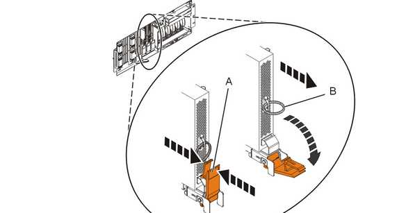
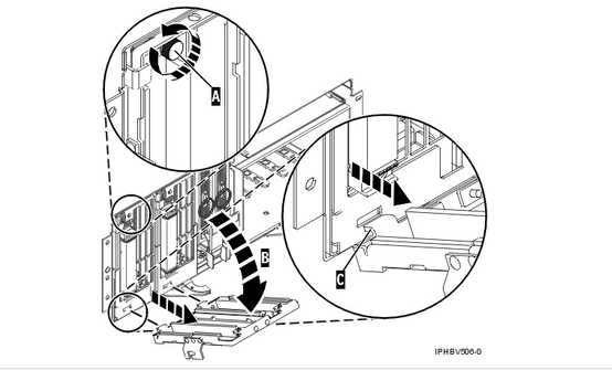
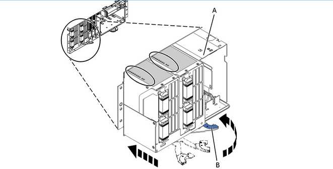
5、Remove the Voltage Regulator Assemblies
- Squeeze the top of the latch (A) to release it, then rotate the latch out and then down.
- Grasp the pull ring (B) and slowly pull the voltage regulator out of the enclosure. NOTE: Pulling the voltage regulator assembly out of the card enclosure requires a large amount of force. The voltage regulator assembly is of substantial weight, so grasp it firmly when it is free of the card enclosure.
- Repeat these steps until all voltage regulator assemblies have been removed.
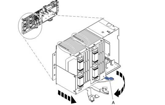
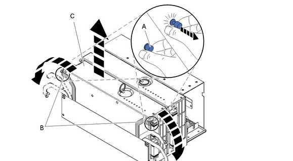
6、Remove the System Backplane Assembly
Note: A shipping support clamp has been installed on your server. Removal is not required. This clamp will not interfere with the drawer front covers or machine operation. If removed, store for re-use when the server is relocated.
- Push the blue lever to the left and out from the system (A) to unlock the system backplane assembly.
- Pull the system backplane assembly out of the system using both hands.
Attention: The system backplane assembly weighs 35 lbs and should not be pulled out using the blue lever. Grasp the backplane assembly firmly with both hands when it is free of the
7、Identify the Failing DIMM
If you are removing the DIMMs because of a system failure, look at the LEDs (A) located on top of the system processor assemblies to identify the location of the failing DIMMs. To illuminate the location LED for the failing DIMM, press the LED actuator button (B).
Attention: The actuator button must be used within 20 minutes after the system backplane assembly is removed from the system. The assembly retains the energy to light the LEDs for 40 seconds after the actuator button has been pressed.
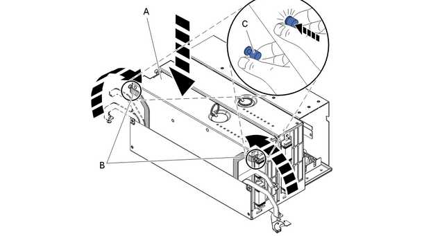
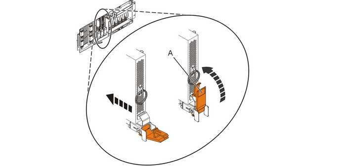
8、 Remove the System Processor Assembly
- Unscrew the two blue thumbscrews, pivot the processor alignment face plate out, and then remove it.
- Pull the locking knobs (A) out to the unlocked position.
- Push the locking arms (B) down and out to unlock the processor card assembly.
- Lift the processor card assembly (C) out of the system backplane assembly.
9、Remove the System Processor Assembly Cover
- Unlock the two retaining knobs (A) on the system processor assembly.
- Slide the cover (B) back.
- Lift the cover off of the assembly.
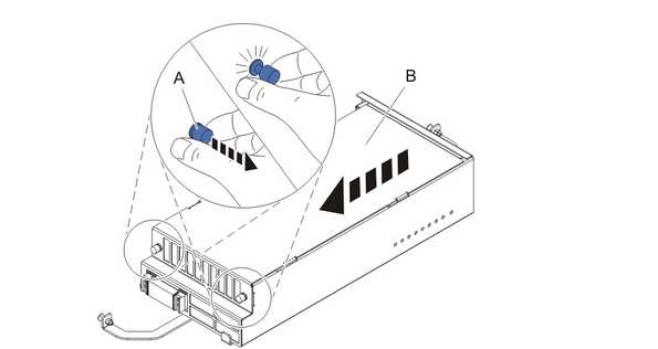
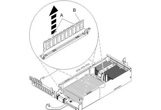
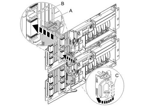
10、 Remove the Memory DIMM
- Remove the mylar cover, if installed, that is covering the memory DIMMs.
- Locate the memory DIMM you want to remove.
- Unlock the memory DIMM by pushing the connector tabs (A) out and then down. The tabs‘ lever action forces the memory DIMM (B)out of the connector.
- Lift the memory DIMM out of the connector.
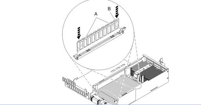
11、 Install the Memory DIMM
- Ensure that the connector locking tabs (A) are pushed out into the unlocked position before installing a new memory DIMM.
- Carefully grasp the memory DIMM (B) along two edges and align it with the connector.
Attention: Memory DIMMs are keyed to prevent a DIMM from being installed improperly. Note the locations of the key tabs within the DIMM connector before attempting to install the DIMM.
- Push the memory DIMM firmly into the connector until the connector locking tabs engage.
- If you are installing any Tall DIMMs, place the mylar cover over the DIMMs in the processor card to prevent the DIMMs from contacting the lid. NOTE: If you replace Tall DIMMs with regular-sized modules, remove the mylar cover. Failing to remove the mylar cover might restrict airflow in the unit.
12、 Install the System Processor Assembly Cover
- Place the cover (B) on the system processor assembly.
- Lock the two retention knobs (A).
13、 Install the System Processor Assembly
- Place the processor assembly (A) into the system backplane assembly, and then lock it into place with the locking arms (B).
- Press the locking knobs (C) in to the locked position.
- Install the processor alignment face plate.
14\ Install the System Backplane Assembly
- Align the system backplane assembly with the slot in the system.
- Slide the system backplane assembly into the system (A).
- Push the blue lever (B) to the right and in toward the system to lock the system backplane assembly.
15\ Install the Voltage Regulator Assemblies
- Ensure that the voltage regulator assembly latch (A) is rotated out and down into the unlocked position.
- Carefully grasp the voltage regulator assembly and slide it into the enclosure.
- When the voltage regulator assembly is all the way into the card enclosure, rotate the latch (A) up into the locked position.
- Repeat these steps until all voltage regulator assemblies have been installed.
|
16\ Install the Control Panel or Control Panel Filler
In the enclosure you are servicing, carefully slide the control panel or, if present, the control panel filler, into the control panel bay (B)until you feel the locking tabs (A) lock in place.
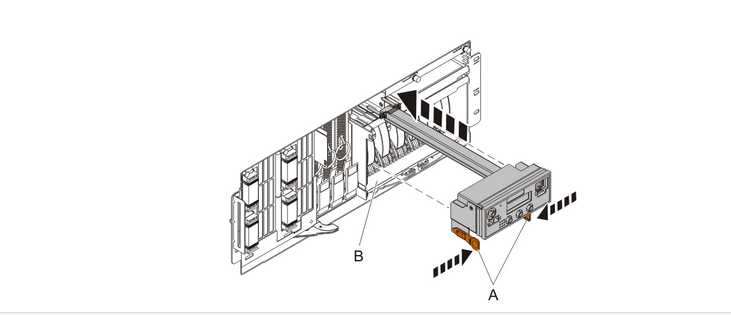
17\Connect SMP Cable
- Align the guide pins (A) with the connectors (B) on the system unit.
- Using the handle (C), carefully push the SMP processor cable into the system unit connector.
Repeat these steps for all SMP cable connectors that are present on the system you are servicing.
18\ Install the Front Cover
- Position the cover on the front of the system unit so that the tab on the left side of the cover is in the matching slot (A) on the left side of the system unit.
- Tighten the thumbscrew (B) on the right side of the cover.
- Close the front rack door.
19\Install the power cords
If you removed the power cords, reinstall the power cords for all of the processor enclosures.
Install the cords in the following order:
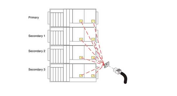
- Secondary 2
- Secondary 3
- Primary
- Secondary 1
20\ Verify the repair
四、注意事项
1、通过HMC管理的多柜多分区的系统注意确认柜子号是否准确(一般没有变更)。
2、1GB内存的更换存在bug会导致更换之后重很多内存deconfig,可以使用2GB或4GB替代所以。
3、更换重启之前,建议通过celogin1用户登陆ASMI清理掉deconfig的内存信息和error信息。
4、混插1g和2g内存可能导致B181B31B FSPSP16和FSPSP04错误。
5、多柜子更换注意保护连接线阵脚完好否则报错无法启动机器。
IBM 9117-MMA-更换内存案例
原文:https://www.cnblogs.com/dahaoran/p/ibm.html