If you are new to ARM development, it is recommended to follow this short tutorial and learn how to build a simple test executable program that will blink a LED.
Note: this tutorial was created with the GNU Tools for ARM Embedded Processors toolchain in mind. Only when using this toolchain the build is guaranteed to succeed. Using other toolchains might be possible, but small changes might be necessary in the source code and in the linker options.
Note2: this tutorial requires a recent version of the STM32F4 template, not older than 20150807.
Before creating a new project, please be sure you checked all prerequisites described in the How to install GNU MCU Eclipse? page, especially the need to install the build tools if you use Windows as your development platform.
It is also recommended to set the workspace preferences and to install the desired CMSIS packs.
Note: the multi-LED template is currently available only for ST32F4, and only for C++, since it allows to easily instantiate multiple BlinkLed objects.
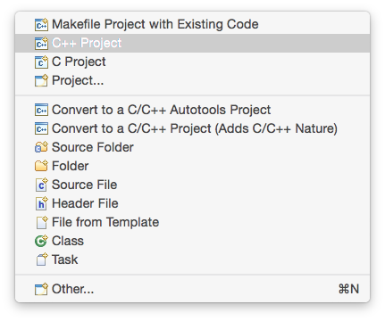
To create a new project, go to Eclipse menu, File → New (or the button in the upper left corner), and select the C++ Project:
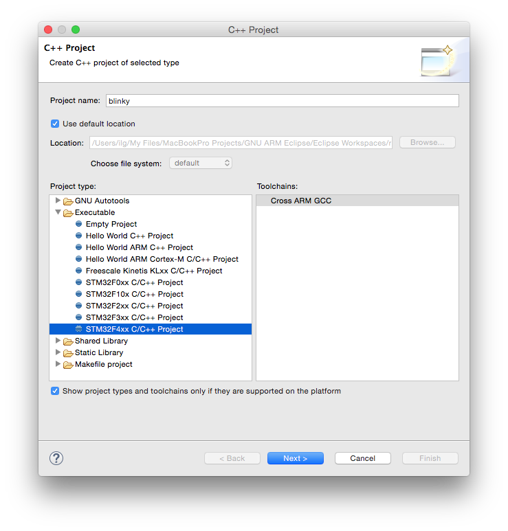
In the C++ Project window:
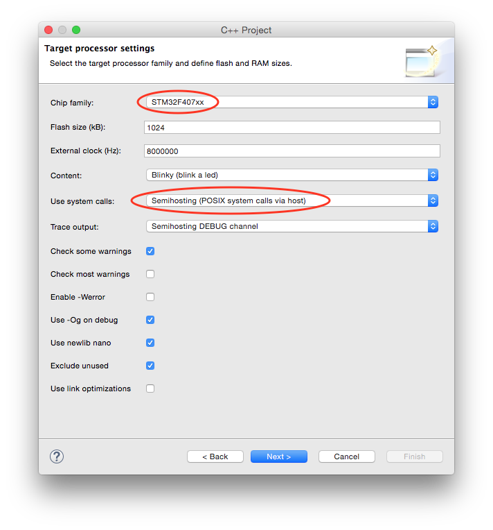
In the Target processor settings window be sure to:
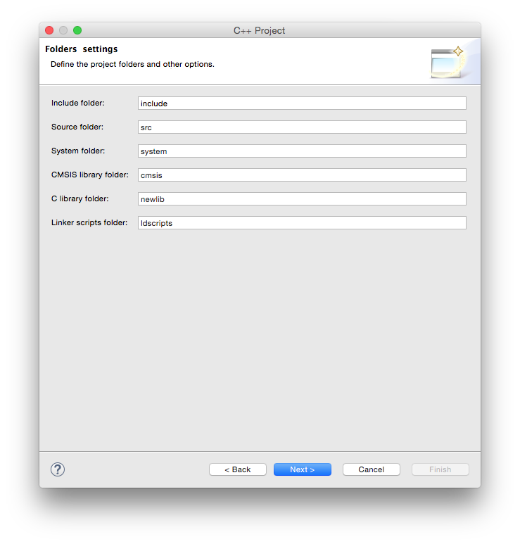
In the Folders page leave the suggested folders unchanged and click the Next > button.
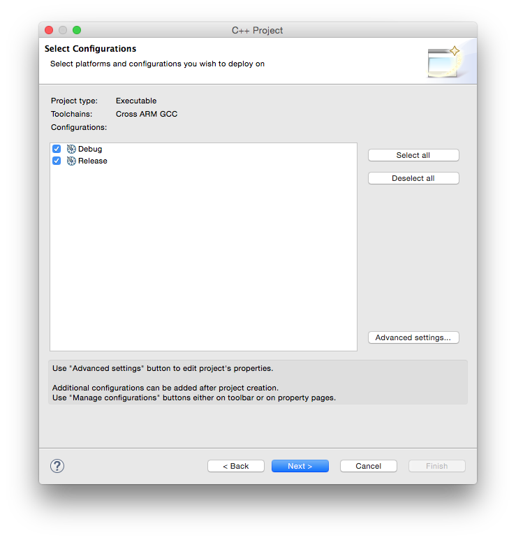
In the Select Configurations page leave the suggested Debug/Release configurations checked and click the Next > button.
In the Cross GNU ARM Toolchain window:
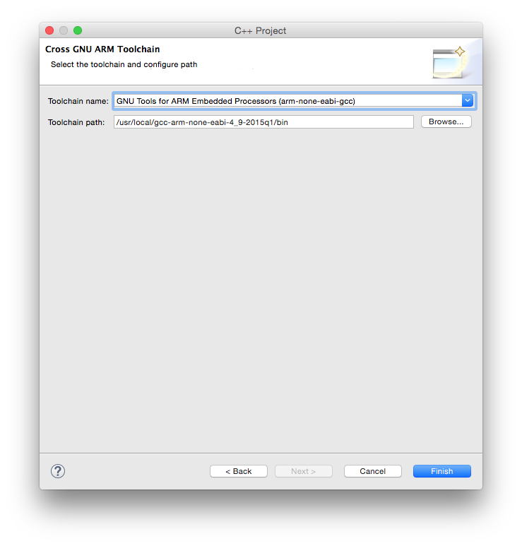
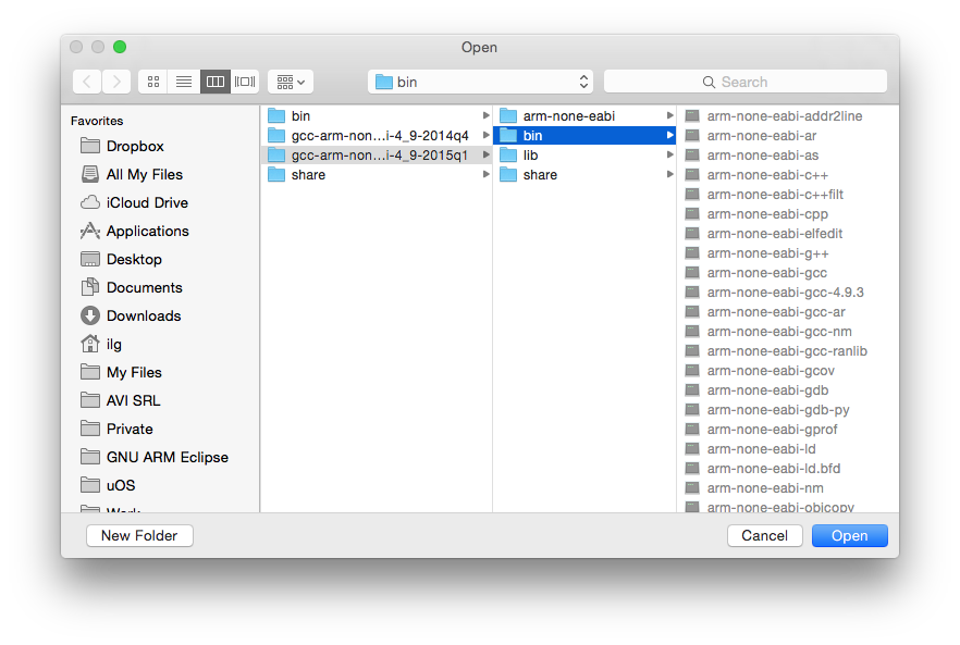
Note 1: when selecting the path, be sure you select the /bin folder where the programs with long, prefixed names are stored, and not the inner /bin folder where the short name programs may be available.
Note 2: DO NOT SKIP this step, it is mandatory to have a correct toolchain path defined in order for the build to complete correctly.
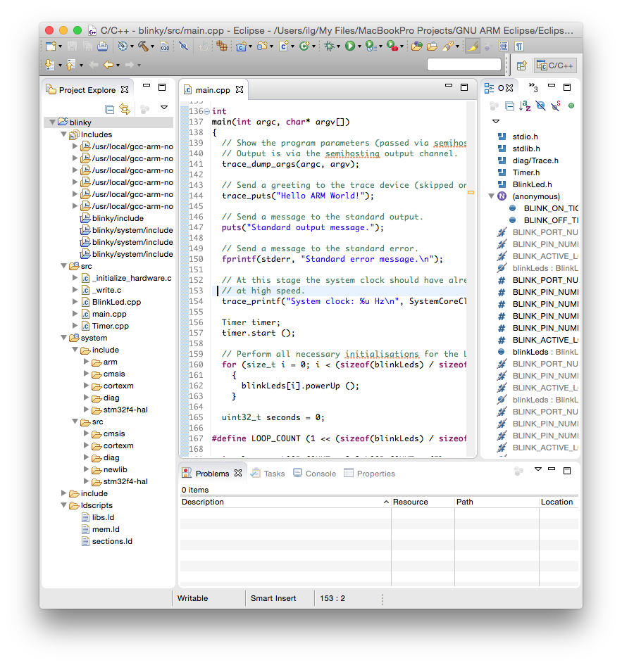
The result of the wizard is a simple project, with a main() function printing a greeting on the standard output.
To start the build:
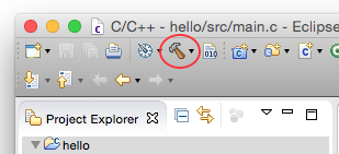
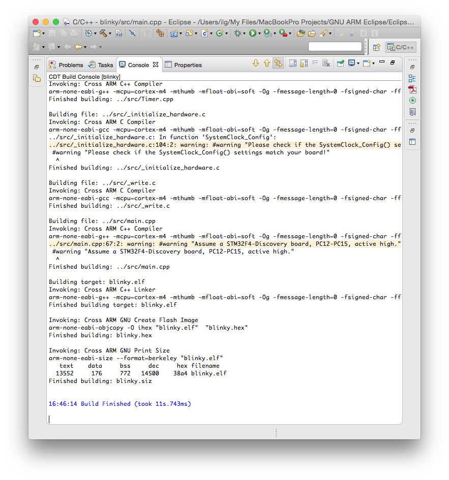
The build process should leave in the Console window a listing like this:
The files created by the build process are left in a folder named by the name of the configuration, for example Debug or Release.
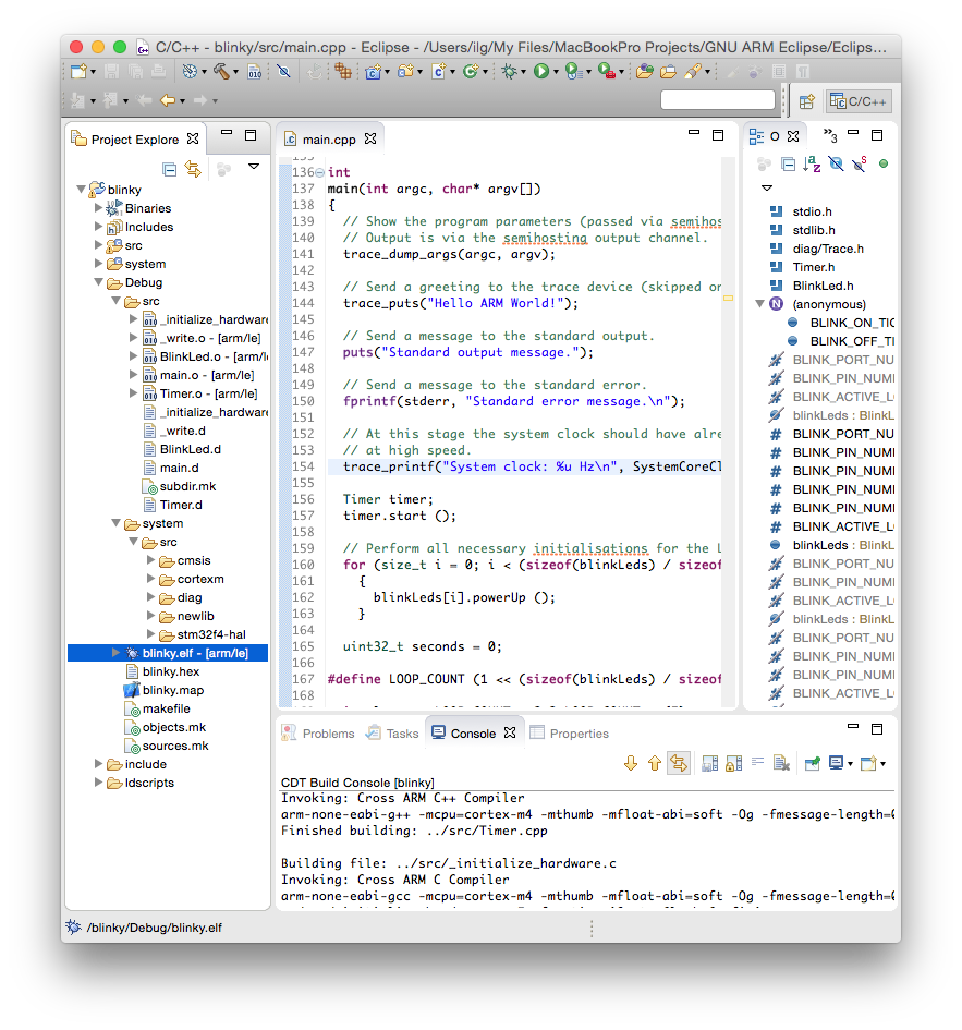
As seen above, the Debug folder is populated with:
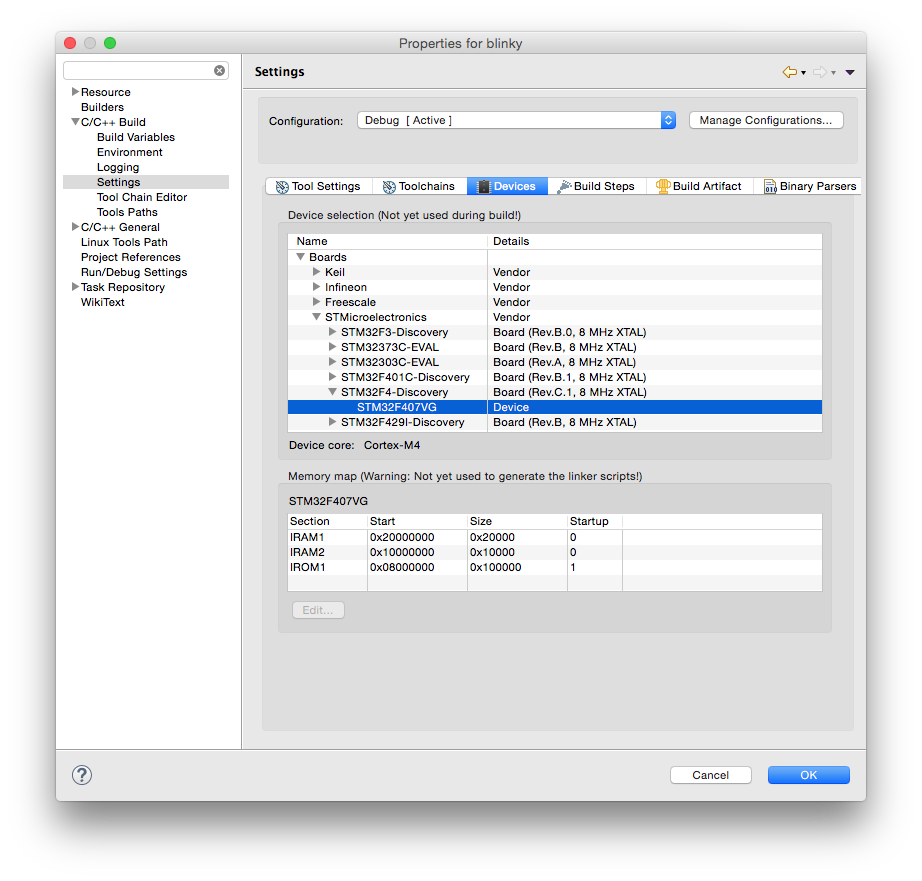
Although optional, it is highly recommended to assign a board and a device to the project, using the packs definitions. If you did not do it before, install the STM32F4 package, as explained in the Packs Manager page.
To assign the board and device:
The most convenient way to run this test is to use the QEMU Debugging plug-in. Actually, with the latest plug-ins, you can directly Run the application, you do not need to Debug it.
As for any debugging plug-in,
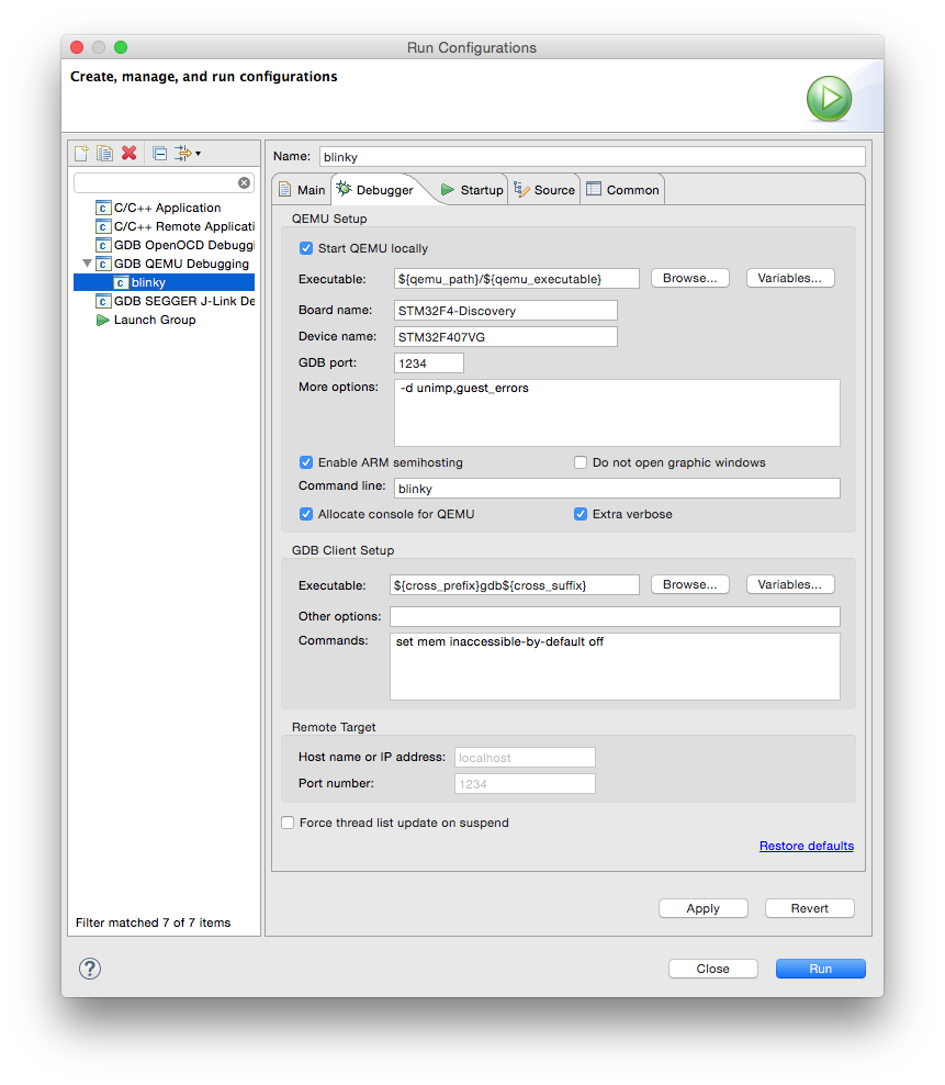
When done, click the Run button.
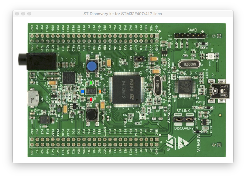
If you did not disable the graphic windows, an animated image of the board is shown, with the 4 LEDs blinking.
The QEMU process also displays some information in its console:
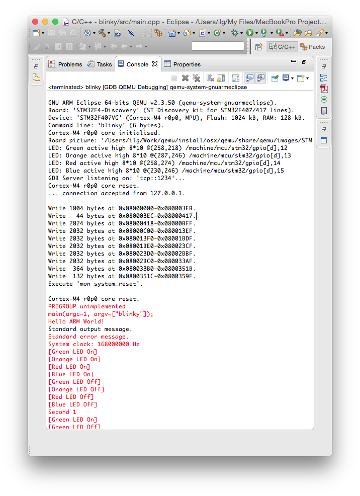
Contrary to usual POSIX environments, like GNU/Linux, embedded systems usually do not provide standard input/output devices. In the code generated by the template, the output of the printf() calls, including trace_printf(), is redirected to a special debugging channel implemented by most debuggers, using the semihosting protocol.
Once you checked the development environment to be functional, proceed with creating real projects using the STM32Fx templates, Freescale KLxx templates, or, if your target processor is not yet supported, using the Generic Cortex-M template.
The usual sources for build failures are:
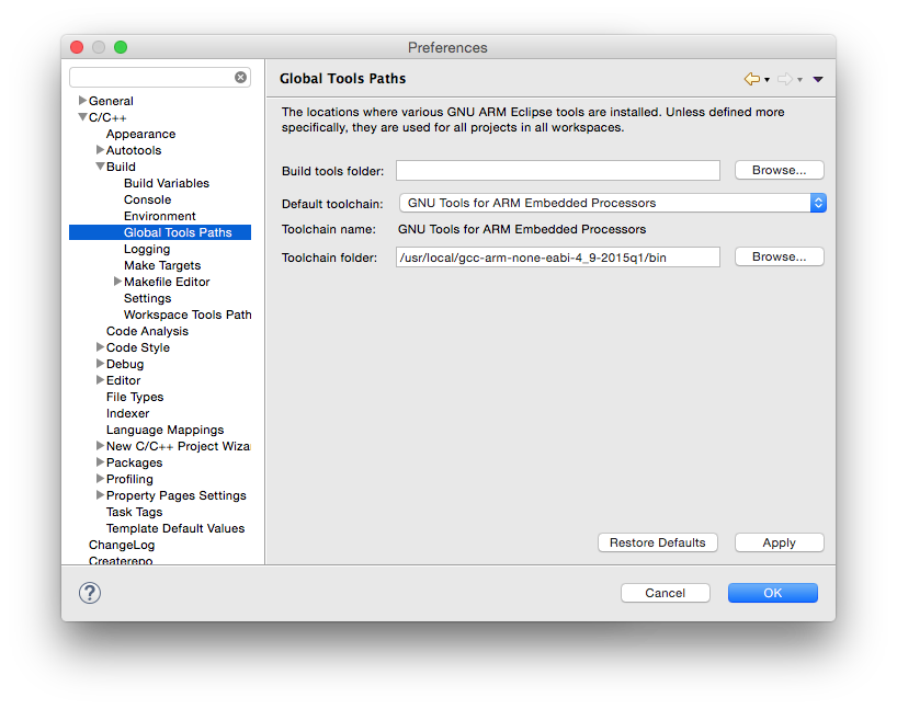
Set the toolchain path for all projects and workspaces.
If something went wrong and you cannot build the project, please check the How to use, the FAQ and the Known issues pages. If you do not find the answer to your question, please read the Support page on how to record a support request in the Support tracker. Do not post comments on this page unless they are related to the text (the phrasing is not correct, you discovered typos, etc).
Last modified on Wed Apr 25 17:59:20 2018 UTC.
Tutorial: Create a Blinky ARM test project(创建一个闪灯的arm测试项目)
原文:https://www.cnblogs.com/schips/p/12375684.html