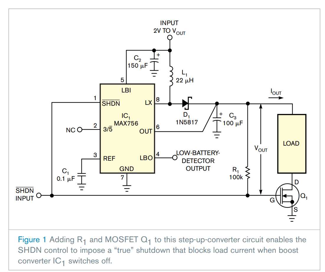
The step-up switching-converter circuit in Figure 1 presents a familiar problem: If you shut down boost converter IC1 by pulling its ![]() input low, external inductor L1 and forward-biased Schottky diode D1 allow the load to continue drawing current. For battery-powered applications that present a heavy load—300 mA, for example—this unwanted dc-current path may quickly drain the battery. Adding an N-channel MOSFET, Q1, and a 100-kΩ resistor, R1, solves the problem by opening the unwanted current path during shutdown. The resulting circuit is suitable for battery-powered-system applications in which a microcontroller handles the power management.
input low, external inductor L1 and forward-biased Schottky diode D1 allow the load to continue drawing current. For battery-powered applications that present a heavy load—300 mA, for example—this unwanted dc-current path may quickly drain the battery. Adding an N-channel MOSFET, Q1, and a 100-kΩ resistor, R1, solves the problem by opening the unwanted current path during shutdown. The resulting circuit is suitable for battery-powered-system applications in which a microcontroller handles the power management.
Asserting a low logic level on the ![]() input simultaneously shuts down the switching converter, a MAX756, and turns off the MOSFET, thereby blocking load current by removing the load‘s ground connection. When the
input simultaneously shuts down the switching converter, a MAX756, and turns off the MOSFET, thereby blocking load current by removing the load‘s ground connection. When the ![]() signal deasserts, the 100-kΩ pullup resistor turns on the MOSFET by pulling the MOSFET‘s gate high. With its ground reconnected, the load then draws current from the activated boost-converter circuit.
signal deasserts, the 100-kΩ pullup resistor turns on the MOSFET by pulling the MOSFET‘s gate high. With its ground reconnected, the load then draws current from the activated boost-converter circuit.
For optimum results at high load currents, select a logic-level MOSFET for Q1 that presents a reasonably low on-resistance. The MOSFET‘s drain-to-source breakdown voltage should also be able to withstand at least twice the maximum output voltage you expect from the boost converter. If necessary, you can reduce the MOSFET‘s effective on-resistance by connecting two or more MOSFETs in parallel.
External components provide true shutdown for boost converter
原文:http://www.cnblogs.com/shangdawei/p/4128132.html