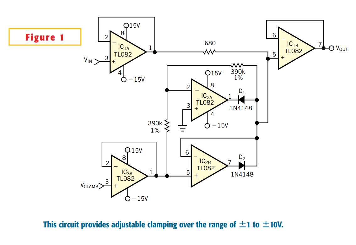
The easy way to clamp a signal to a given value is to use two zener diodes, connected back-to-back. This method has several disadvantages. The accuracy of the clamping depends on the tolerance of the zener diodes, and the clamping is not adjustable, except by changing diodes. The circuit in Figure 1 is a bipolar clamper with a range of ±1 to ±10V, with the clamping level a function of the input VCLAMP. IC1A, IC1B, and IC3Aare unity-gain buffers. IC2A is a positive clamper, and IC2B is a negative clamper.Figure 2 shows the transfer function, with VCLAMP set at –5V. You can change VCLAMPover the range of –1 to –10V and thereby change the clamping level. If VIN is within –VCLAMP to +VCLAMP, then VOUT=VIN. If VIN exceeds VCLAMP, then VOUT=VCLAMP. To explain how the circuit works, assume four cases, with four values of VIN. Basically, the circuit works in two modes: the linear mode, in which diodes D1 and D2 are open switches, and the clamped mode, in which the diodes are closed switches. Table 1gives results for the four cases. In Case A, the input is 7V, VCLAMP is –5V, D1 conducts, and D2 is an open switch. The feedback loop around IC2A regulates the anode of D1 to 5V and the output of IC2A to 4.4V. In cases B and C, both diodes are open switches. In Case D, D2 conducts, and D1 is an open switch.
Circuit forms adjustable bipolar clamp
原文:http://www.cnblogs.com/shangdawei/p/4128383.html